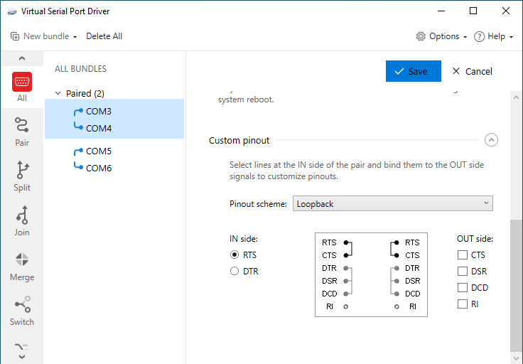
At the “Custom pinout” tab section, you can choose from signal lines pinout presets or create your own pinout preset just in a couple of clicks.
Pinout presets:
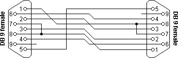
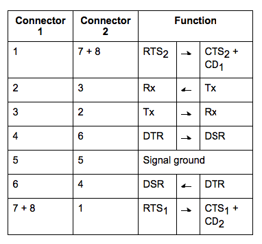
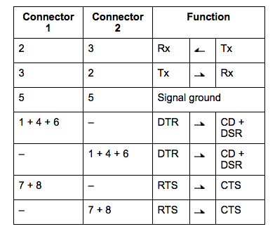
Standard: the default signal lines pinout RS232 null modem scheme with partial handshaking:
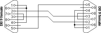
Loopback: the RS232 null-modem scheme with loopback handshaking:
Setting the custom pinout:
- On the “All” tab, select the virtual serial pair you want to set the custom pinout for.
- Use the radio buttons to select the RTS or DTR signal line on the IN side, then use the checkboxes at the OUT side to set the pinout to your liking.
- To save settings, click the “Create” button. The name to the new custom pinout will be assigned automatically (e.g. DTR->CTS,DCD,RTS->DSR), and it will be available as a preset option for other virtual port pairs.
Note: Other null-modem schemes are available here.
Signal lines description:
- RTS (Request to Send) – This signal is asserted (logic ‘0’, positive voltage) to prepare the DCE device for accepting transmitted data from the DTE device. Such preparation might include enabling the receive circuits9 or setting up the channel direction in half-duplex applications. When the DCE is ready, it acknowledges by asserting Clear to Send.
- DTR (DTE Ready) – This signal is asserted (logic ‘0’, positive voltage) by the DTE device when it wishes to open a communications channel. If the DCE device is a modem, the assertion of DTE Ready prepares the modem to be connected to the telephone circuit, and, once connected, maintains the connection. When DTE Ready is de-asserted (logic ‘1’, negative voltage), the modem is switched to “on-hook” to terminate the connection.
- CTS (Clear to Send) – This signal is asserted (logic ‘0’, positive voltage) by the DCE device to inform the DTE device that transmission may begin. RTS and CTS are commonly used as handshaking signals to moderate the flow of data into the DCE device.
- DSR (DCE Ready) – When originating from a modem, this signal is asserted (logic ‘0’, positive voltage) when the following three conditions are all satisfied:
- The modem is connected to an active telephone line that is “off-hook”
- The modem is in data mode, not voice or dialing mode
- The modem has completed dialing or call setup functions and is generating an answer tone
- DCD (Carrier Detect) – This signal is relevant when the DCE device is a modem. It is asserted (logic ‘0’, positive voltage) by the modem when the telephone line is “off-hook”, a connection has been established, and an answer tone is being received from the remote modem. The signal is de-asserted when no answer tone is being received, or when the answer tone is of inadequate quality to meet the local modem’s requirements (perhaps due to a noisy channel).
- RI (Ring Indicator) – his signal is relevant when the DCE device is a modem and is asserted (logic ‘0’, positive voltage) when a ringing signal is being received from the telephone line. The assertion time of this signal will approximately equal the duration of the ring signal, and it will be de-asserted between rings or when no ringing is present.